How to Read P&ID
In this Article we will develop the rule of how to read P&ID. The P&ID is the diagram the most frequently used by the operators, maintenance and safety.
- Legends and P&ID Abbreviations.
- Margins.
- Equipment.
- Effluent Routes.
- Instrument Location.
- ControlLoop.
LEGENDS AND ABBREVIATIONS.
To comprehend the PID, see the legends and abbreviations given with it. As presented below, certain symbols might not be Universal ones as per ANSI/ISA’s S5.1-1984(revision 2009), BS5070 and ISO 10628 but this occur and in that case, just think, and compare(association with the different element) and everything will be okay.
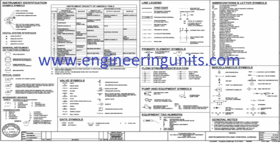
Instrumentation detail varies with the degree of design requirement and project phase. For example, basic or conceptual designs, often named process flow diagrams (PFD), offer fewer detail than completely developed piping and instrumentation diagrams (P&IDs).
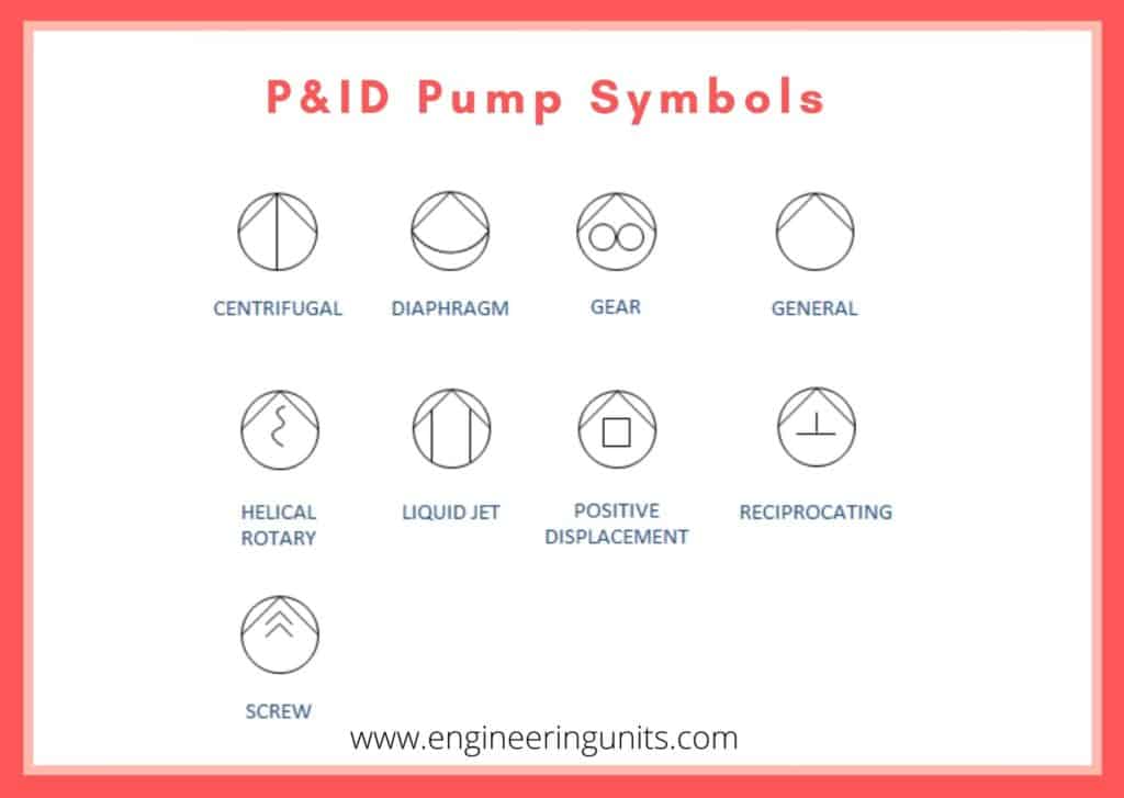
General of the legend will contain the below sections:
- Abbreviation.
- Equipment symbols.
- Piping symbols.
- Piping Connection.
- Line Identification.
- Vessel symbols.
- Heat Exchanger symbols.
- Pump symbols.
- Instrument symbols.
- Instrument Identification.
- Valve symbols.
- Piping Connection.
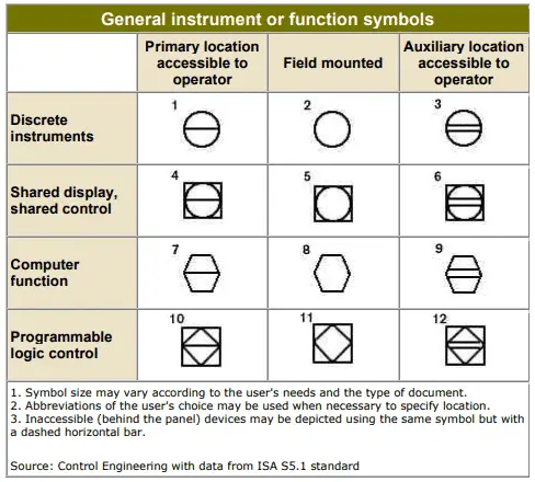
General Instruement or function Symbols 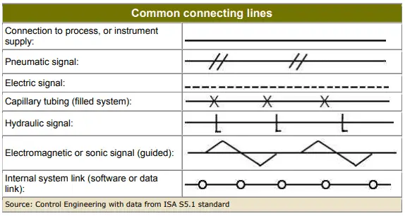
Common Connecting Lines
MARGINS in P&ID.
The margins of the PID provide info on the PID’s revisions, unique PID document number, revision history, explanations and notes.
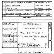
The PID number is a unique number which recognizes the PID. It is situated in the bottom right-hand corner of the margin, along with the title, facility name of the issuer (engineering firm, vendor, EPC contractor), revision stamp and revision number (or letter). It is very important to always check you have the latest revision.
The changes made to the PID since the last revisions are sometimes shown in there vision table in the bottom margin.
EQUIPMENT in P&ID
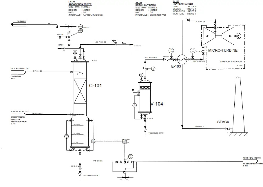
Equipment is the main items shown in a P&ID to perform the process required treatment. The plant equipment is shown in the P&ID by an icon showing the equipment in basic manner. Usually they are identified by a name and unique tag (Unique identifier that is assigned to a field device, skid or equipment).
The following requirements will bedescribed under equipment description:
- Vessel item Tag.
- Service.
- Size(diameter(s) and length).
- Design pressure and design temperature.
- Indication of insulation.
- Line number of vessel trim (this applies to LG & LC connections, vents, sample connections, etc.).
- Indication of cladding and lining (if any).
- Capacity if a pump.
- Material.
- …
EFFLUENT ROUTES.
The process flows are specified by the flowlines. Where conceivable, the incoming flowline is located on the left and the leaving flowline on the right. Tags or title boxes at the ends of the lines provide information on the sources and destinations of the flows.
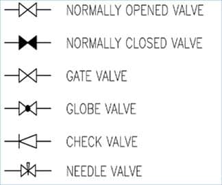
The flows are directed by normally-open valves. The bodies of these valves are normally not filled, whereas the bodies of the normally-closed valves are filled for further details check the below picture.
INSTRUMENT LOCATIONS.
The next table shows the typical instrument symbols and the measures available, field mounted and remote to the operator.

The most significant feature of the instrument symbols is the difference in their positions. The operator must know the positions of the main local equipment.
An instrument shown in a circle indicates that the instrument is mounted directly on the equipment.
A circle with a horizontal line through it specifies that the instrument is mounted on (wired to a local PLC) a local control panel. This panel is installed in an accessible location close to the equipment it operates.
A hexagon with a horizontal line indicates a computer function.
Each instrument designation is given a loop tag and identification letters to understand the tag as we mentioned above check the legend of the P&ID.
The below table contains some instrument abbreviations used with P&ID symbols in instrumentation diagram.
| Instrument abbreviation | Expansion | Function Performed |
| FC | Flow Controller | Flow measurement and control |
| LC | Level Controller | Level Control |
| FE | Flow Element | Flow sensor |
| LAH | Level Alarm High | Indicating High Level |
| LAHH | Level Alarm High High | Indicating High High Level |
CONTROL LOOP.
The control loops are one of the most important parts of a PID. “Control loop” is a general term for all the elements involved in controlling a process parameter, like tank levels or vapour flows. This includes all the hardware and software associated with this control function.
The hardware items in a control loop are termed “instruments”.
It is important to remember that most control loops can be broken down into three parts:
• The measurement element.
• The controller.
• The control system.
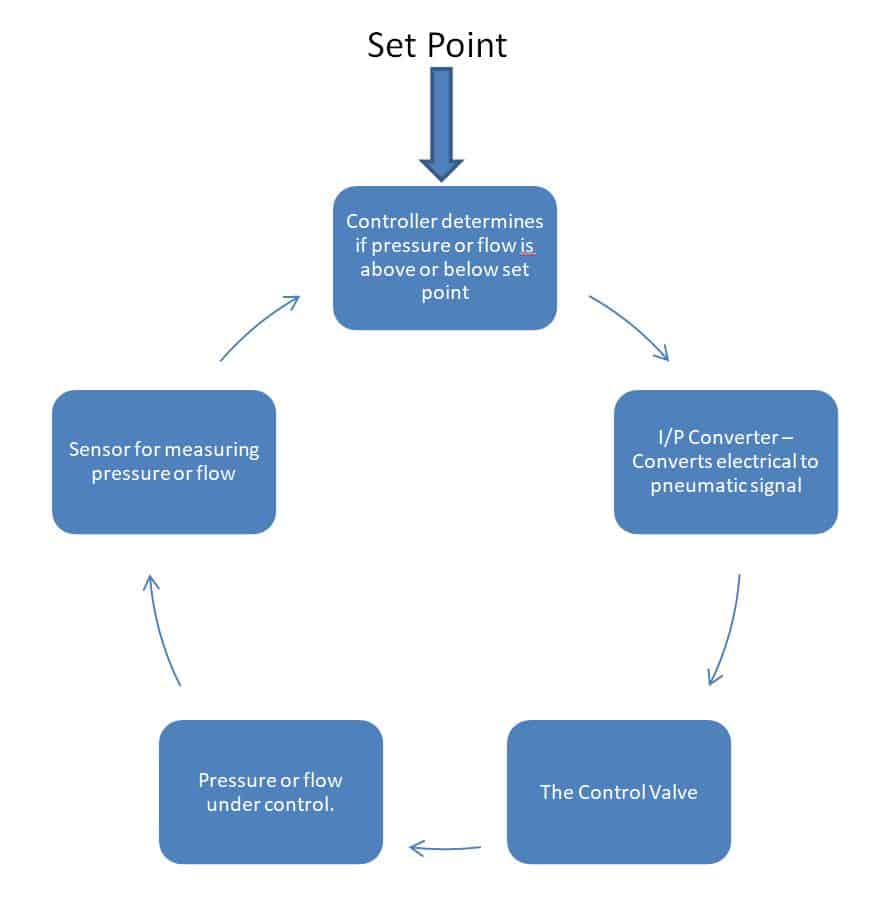
A good understanding of a basic control loop will help you to understand more complicated control loops.
The measurement element.
The measurement element produces a signal which represents the process variable being controlled. The commonly used process variables are: level, pressure, flow and temperature. The measurement element is connected to a transmitter which sends a signal to the controller. The control signal can take the form of an overhead pneumatic signal, an electric signal (milliamps) or even a remote radio signal, depending on the case.
The controller.
The controller determines the control adjustments needed. This is done by comparing the measured value to a setpoint (SP), which is the required setting for a process variable. The controller adapts the system until the value of the process variable is equal to the setpoint.
A control system.
A control system is any process equipment which can be modulated to change a measured parameter. The control system changes the measured variable. Valves are the most common control systems. For the temperature control these valves control the vapour flows, for example.
They can also take the form of switches, pumps, fans, or electric heating devices and other control devices. Motor speed controllers are also control systems.
It is important to remember that the adjustments made to the control point will modify the variable measured.
Each control loop is given a unique number for differentiate it from other control loops.
A control loop may consist of a single element (e.g. a local pressure gauge), or it may have many different elements (e.g. an automatic flow controller).
A control loop may include detectors, transmitters, controllers, converter I/P,valves, etc.